
Sending and receiving multiple bytes of information efficiently between microcontrollers, sensors or computers requires the design of a communication protocol. We have by example TCP and UDP protocols, which are the basis of internet data exchange.
A communication protocol consists of a well designed data pattern. We can’t just send data bytes and hope someone understand them. Some protocols define fixed data length, others more complicated are designed for variable data length. For example, the TCP protocol is defined as:
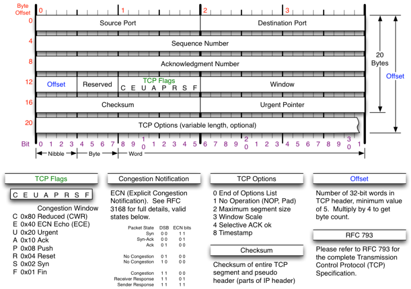
It becomes clear that if we want to transmit complex data, we have to conform with a protocol or create one. Creating one it’s not complicated, the easiest protocol is just a fixed length data sequence that provides a known header.
Let’s create a protocol to send color information to a microcontroller in RGB format, with the goal of controlling a RGB Led. First we need to understand the Red Green Blue color format, for each component we have a possible value between 0 – 255, meaning that each component has a resolution of 8 bits. So… the RGB format defines a 24 bit color.
Our protocol needs to implement a minimum of 3 bytes (1 byte equals 8 bits) to contain color data in RGB format. We also require a header to identify the protocol, and optional but extremely suggested is the use of a checksum byte as a validation method, this gives us a protocol with a fixed value of 5. Every package we send/receive will have a length of 5 bytes. Validation gives us assurance that the data we receive is not corrupted (sometimes by unknown causes we might have data corruption, for example: a bit value changes by electromagnetic effects in the transmission line, the color might change dramatically by this cause). The following table illustrates the protocol we’re going to use:

We are going to employ two Arduinos for testing. One will have 3 potentiometers, one for each color component (Red, Green, Blue), the other one will have an RGB Led connected to it. They will be connected through their UART pins (Arduino Serial Library employs UART).

The following code will be downloaded to the first Arduino (the one with the potentiometers):
const uint8_t bufferSize = 5;

uint8_t buffer[bufferSize];

void setup(){
  while(!Serial);
  Serial.begin(115200);

  //we define our header byte only once, we're not going to change it
  buffer[0] = 0x7E;
}

void loop(){
  //Read potentiometer values
  int r = analogRead(0);
  int g = analogRead(1);
  int b = analogRead(2);

  //analogRead() returns a 10 bit value, we need to scale it to a 8 bit value.
  //10 bit max value is 1023, 8 bit max value is 255.
  //We have two options:
  //1 - Divide our 10 bit value by 4, to obtain and effective 8 bit value.
  //2 - Bitshift Right by 2, to obtain and effective 8 bit value.

  //Dividing is easier to understand, but computes slowly
  buffer[1] = r / 4;
  buffer[2] = g / 4;
  buffer[3] = b / 4;

  /*
  //Bitshifting is faster, but a little harder to understand.
  //After the shifting we AND the result because the value is a 16 bit value
  //int is a signed 16 bit value in Arduino 8 bit boards.
  buffer[1] = (r >> 2) & 0xFF;
  buffer[2] = (g >> 2) & 0xFF;
  buffer[3] = (b >> 2) & 0xFF;
  */

  buffer[4] = checksum();

  //We send all bytes stored in the buffer
  Serial.write(buffer, bufferSize);

  delay(100);
}

//We perform a sum of all bytes, except the one that corresponds to the original
//checksum value. After summing we need to AND the result to a byte value.
uint8_t checksum(){
  uint8_t result = 0;
  uint16_t sum = 0;

  for(uint8_t i = 0; i < (bufferSize - 1); i++){
    sum += buffer[i];
  }
  result = sum & 0xFF;

  return result;
}
Reading a byte stream (a buffer) is tricky. We need to consider several factors. So we have to design a flowchart for this endeavour:
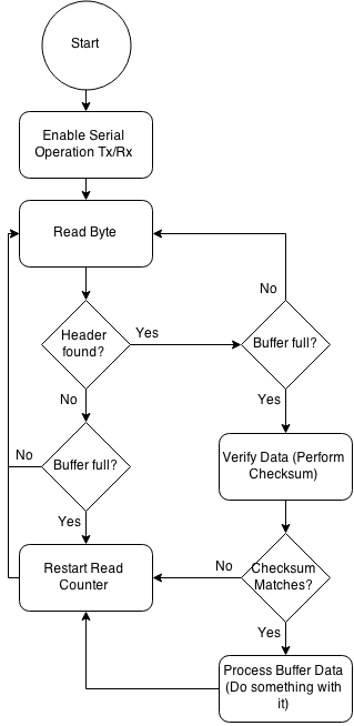
The following code will be downloaded to the second Arduino (the RGB Led Controller):
const uint8_t header = 0x7E;
const uint8_t bufferSize = 5;

uint8_t buffer[bufferSize];
uint8_t readCounter;
uint8_t isHeader;

//Flag that helps us restart counter when we first find header byte
uint8_t firstTimeHeader;

void setup(){
  while(!Serial);
  Serial.begin(115200);

  readCounter = 0;
  isHeader = 0;
  firstTimeHeader = 0;

  pinMode(11, OUTPUT);
  pinMode(10, OUTPUT);
  pinMode(9, OUTPUT);
}

void loop(){
  //Check if there is any data available to read
  if(Serial.available() > 0){
    //read only one byte at a time
    uint8_t c = Serial.read();

    //Check if header is found
    if(c == header){
      //We must consider that we may sometimes receive unformatted data, and
      //given the case we must ignore it and restart our reading code.
      //If it's the first time we find the header, we restart readCounter
      //indicating that data is coming.
      //It's possible the header appears again as a data byte. That's why
      //this conditional is implemented, so that we don't restart readCounter
      //and corrupt the data.
      if(!firstTimeHeader){
        isHeader = 1;
        readCounter = 0;
        firstTimeHeader = 1;
      }
    }

    //store received byte, increase readCounter
    buffer[readCounter] = c;
    readCounter++;

    //prior overflow, we have to restart readCounter
    if(readCounter >= bufferSize){
      readCounter = 0;

      //if header was found
      if(isHeader){
        //get checksum value from buffer's last value, according to defined protocol
        uint8_t checksumValue = buffer[4];

        //perform checksum validation, it's optional but really suggested
        if(verifyChecksum(checksumValue)){
          //We'll employ PWM to control each RGB Component in the Led
          analogWrite(11, buffer[1]);
          analogWrite(10, buffer[2]);
          analogWrite(9, buffer[3]);
        }

        //restart header flag
        isHeader = 0;
        firstTimeHeader = 0;
      }
    }
  }
}

//This a common checksum validation method
//We perform a sum of all bytes, except the one that corresponds to the original
//checksum value. After summing we need to AND the result to a byte value.
uint8_t verifyChecksum(uint8_t originalResult){
  uint8_t result = 0;
  uint16_t sum = 0;

  for(uint8_t i = 0; i < (bufferSize - 1); i++){
    sum += buffer[i];
  }
  result = sum & 0xFF;

  if(originalResult == result){
     return 1;
  }else{
     return 0;
  }
}
Test the code, and watch as you move the potentiometers how the RGB Led changes its color!
By creating this protocol, we can now easily send and receive data that corresponds to the RGB Led Color. Let’s say we need to control other things… well, we can modify our protocol to handle more bytes.
Some ideas to explore: Connecting these Arduinos wirelessly using two Xbees. Connecting one Arduino with a Raspberry Pi to transmit analog sensor data (Raspberry doesn’t have ADC pins, modifying this protocol we could send all arduino’s analog pins values in one package!). With some modifications you could employ this protocol to read several messages from Arduino Ide’s serial console and perform actions, you could recycle some of the code to parse strings.
This example doesn’t just apply for communication between Arduinos, it actually applies to communicate with everything! Say for example you want to control the same RGB Led wirelessly, you have several options here: bluetooth, zigbee, wifi. Actually… many of the current Smart Led Bulbs in the market employ a similar protocol (like the one we described here) to manipulate its color, they map the RGB Color Components in bytes and send them in a defined sequence (they send a little more data of course). These product’s manufacturers depend heavily on a communication protocol.

Hey, I’m trying to make two arduinos talk to eachother through bluetooth. I have 4 analog signals to be transmitted and 8 buttons. Is there a way to send all the button values in one byte instead of 8 different bytes? It seems possible because i have 8 buttons so each button can be send as one bit. I only don’t know how to send and receive it. Any suggestions? Thanks.
LikeLike
Howdy Nemo.
Sorry for the late reply. It’s not hard to do so. You actually got the right idea of mapping a button per bit.
Like: (it’s an idea…)
uint8_t variable = ((digitalRead(button0) ? 1 : 0) << 0) | ((digitalRead(button1) ? 1 : 0) << 1) ; // and so forth…
Now, if you want to send it… you could reuse most of the code I posted. You would only need to extend the protocol to work with 6 bytes now. Change the buffer size to 6. Assign the button variable to buffer[4]. The checksum should always be assigned in the last buffer member (in your case it is buffer[5]).
Hopefully, this small tip works for you.
LikeLike